IMS ANC
New functions of the Milling and Turning application of the Euclid solid modeling system from MatraDatavision facilitate the creation of a cutting tool library containing geometric and technological information for each tool and to automate the transfer of cutting tool parameters to an NC operation as a function of the selection of a tool.There is cutter data in the Cutter Management System (CMS) that can be migrated to Euclid. However, the data is incomplete and in some cases inaccurate. It is currently being revised.
Furthermore, the cutter and adapter data in the CMS represents only a fraction of the data needed to characterize the manufacturing resources on behalf of Numerical Control (NC) programmers, regardless of the tool they use to define an NC program, be it Euclid or the Automatically Programmed Tool (APT) NC programming language.
At the Fort Worth Division (FWD) of General Dynamics (GD), a significant investment was made to explicitly characterize FWD manufacturing resources. The Numerical Control Data Base Management System (NCDBMS) was initially developed to provide manufacturing resource information to NC programmers using the APT NC programming language. The NCDBMS was among several Model 204 (M204) Data Base Management System (DBMS) based prototypes funded by the CAD/CAM DBMS (CCDBMS) corporate-wide project from 1982 to 1985. This effort was expanded to include a broader scope a of manufacturing data, functions and users, and later funded by the FWD in conjunction with the funding of Automated Numerical Control (ANC), also known as Generative NC, which originated at CVD.
An NCDBMS is needed at CVD, regardless of whether NC programming is to be done manually with APT or interactively with a Euclid, CATIA, UG-II or ComputerVision NC application. If an investment in an NCDBMS is made, then CVD may as well take advantage of ANC and eliminate much of the need for manual or interactive NC programming (2.5 axis parts). Significant improvements in machining efficiency can be achieved with ANC as well. A machine failure can easily be accommodated by re-running the ANC system, and denying it that resource. The ANC system will devise a new optimum fabrication strategy accordingly, and generate all of the necessary machine operations and operator visual aids.
Implementing ANC requires more than just installing the ANC software and training personnel to use it. ANC must be aware of the attributes of all of the fabrication resources that are to be made available to it if it is to select an optimum fabrication strategy. The information must be in digital form if it is to be useful to an ANC system.
There is nothing equivalent to the NCDBMS at CVD, or available commercially. The most economical way to support the implementation of ANC at CVD, it so clone the FWD NCDBMS and install it at CVD. Support from FWD will be required for this endeavor. That support may be funded by FWD in exchange for an implementation of NCDBMS on Oracle instead of M204, which will allow work stations other than those of IBM or compatibles to be used with the NCDBMS. Such a re-hosting of the NCDBMS would be consistent with CVD IRM interests.
The closest thing to an NCDBMS that CVD currently uses is the CMS, which is based on the Relational Information Manager (RIM) DBMS. It would be in the best interest of CVD IRM to re-host CMS on Oracle as well, but that may be unnecessary if the CMS data is migrated to the NCDBMS.
As a means of indicating the degree of information transferability between the CMS and the NCDBMS, and to illustrate the magnitude of data that must be manually entered into the NCDBMS if it is to accurately represent the manufacturing resources of the CVD, the CMS data was compared with the data in the Perishable Cutter Assembly (PCA) portion of the NCDBMS as shown in the Appendix. Many of the CMS attributes are repeated for each cutter type, which is only an instance of a class of tools known to the NCDBMS. The NCDBMS uses a more object-oriented approach in which a number of generic attributes are defined for a class of tools and inherited by each instance of a tool. The description of each instance is augmented by attributes particuliar to it. Consequently, a concatenation of CMS attribute names independent of the specific tools with which they are associated in the CMS was mapped to what appears to be their equivalent attribute names in the NCDBMS as delineated by the NCDBMS PCA "schema" in the Appendix. The schema was scanned, OCRd and the CMS data added.
This was by no means a concerted effort by intimately knowledgeable personnel, but it does indicate that CMS data extraction and NCDBMS (or Euclid) data load routines could be devised to automate the process of transferring attribute values from the CMS to the NCDBMS. However, the representational disparity is such that seems that an entirely manual transfer of data may be the more practical approach, especially given the need to update the CMS data.
The complete implementation of NCDBMS at CVD will require a significant investment. However, the commonality of the fabrication resources between FWD and CVD will mitigate the effort. Benefits may be derived immediately from ANC by limiting ANC to those parts which can be fabricated with one or more of the resources common to both CVD and FWD. The profits derived from these benefits can be used to fund the modification of the NCDBMS data to be more representative of the CVD.
The ANC also eliminates the need to do detailed process planning for 2.5 axis parts (80% of all machined parts). The application of the ANC technology to generative process planning was an integral part of the Integrated Management Systems (IMS) Integrated Process Planning System (IPPS) project. IMS funding reductions have forced the IPPS project to focus only on the use of a variant process planning tool know as Cimtelligence. The cost of implementing Cimtelligence, can be reduced by the implementation ANC, because the Cimtelligence work stations and training could then be limited to that which is necessary to manufacture 3 to 5 axis machined parts and non-machined parts.
The financial condition of the FWD is such that funding for additional ANC development will be terminated 4/5/91. If the ANC team is to remain intact, another source of funding is required. A minimum of 2.3 heads of funding for 3 months is required to sustaining the ANC team until additional funding from Abilene can be had. Given the decision by CVD to develop the Integrated Product Assurance Management (IPAM) system with about 2.5 fewer DSD heads than budgeted, there may be an opportunity to fund the ANC team with the IPAM budget. This will at least keep the ANC team intact to perform on behalf of CVD when the decision is made to implement ANC at CVD.
APPENDIX
PHYSICAL DATA MODEL : PERISHABLE CUTTER ASSEMBLY
FILE NAME : MACHTYPE
MAPS TO ENTITY(S) : MACHINE TYPE can use MACHINE TYPE/HOLDER and uses PCA/MACHINE TYPE
FIELD NAMES
FWD ANC CVD Cutter Management System
ALTERNATE INPUT MEDIUM
ALTERNATE INPUT MEDIUM CAPACITY
AMBIENT TEMPERATURE COMPENSATION
ANTI BACKLASH COMPENSATION
AUTO POSITION COMPENSATION
AXES CONTROLLED QUANTITY AXIS
AXIS DISPLAY TYPE
AXIS REVERSAL METHOD
BEAM AND SAG COMPENSATION
BROKEN TOOL DETECTION METHOD
CIRCULAR INTERPOLATION
CONTOUR FEEDRATE OVERRIDE INCREMENT
CONTOUR FEEDRATE OVERRIDE MAX
CONTOUR FEEDRATE OVERRIDE MIN
CONTROL BLOCK FORMAT
CONTROL DECIMAL FORMAT
CONTROL DIRECTORY SIZE
CONTROL INPUT CODE
CONTROL MEMORY CAPACITY
CONTROL ZERO SUPPRESSION
COOLANT CONTROL METHOD
CUTTER DIAMETER COMPENSATION METHOD
CUTTER LENGTH COMPENSATION METHOD
CUTTING TOOL TYPE
FIXTURE COMPENSATION METHOD
FIXTURE LOCATOR CRITICAL DIMENSION
FIXTURE LOCATOR DEPTH
FIXTURE LOCATOR LATITUDINAL POSITION
FIXTURE LOCATOR LATITUDINAL QUANTITY
FIXTURE LOCATOR LATITUDINAL SPACING
FIXTURE LOCATOR LONGITUDINAL POSITION
FIXTURE LOCATOR LONGITUDINAL QUANTITY
FIXTURE LOCATOR LONGITUDINAL SPACING
FIXTURE LOCATOR TYPE
FIXTURE MOUNT CRITICAL DIMENSION
FIXTURE MOUNT DEPTH
FIXTURE MOUNT LATITUD~NAL POSITION
FIXTURE MOUNT LATITUDINAL QUANTITY
FIXTURE MOUNT LATITUDINAL SPACING
FIXTURE MOUNT LONGITUDINAL POSITION
FIXTURE MOUNT LONGITUDINAL QUANTITY
FIXTURE MOUNT LONGITUDINAL SPACING
FIXTURE MOUNT TYPE
FOLLOWER ERROR MONITOR
HELICAL INTERPOLATION
HORSEPOWER MONITOR HP
HEAD SCREW COMPENSATION
MACHINE HEAD QUANTITY MAX SPINDLES
MACHINE HEAD SELECTION METHOD
MACHINE TYPE
MACHCODE
CONTROL MANUFACTURER
CONTROL MODEL
MACHINE CLASS
MACHINE FAMILY
MACHNAME (< class, family, group)
MACHINE GROUP
MCD COMPATIBLE MACHINE TYPE
POSITION FEEDRATE OVERRIDE INCREMENT
POSITION FEEDRATE OVERRIDE MAX
POSITION FEEDRATE OVERRIDE MIN
PRIMARY INPUT MEDIUM
PRIMARY INPUT MEDIUM CAPACITY
PRIMARY MACHTNE HEAD ORIENTATION
PRIMARY MACHINE HEAD TYPE
RAPID POSITIONING METHOD
SPINDLE GROWTH COMPENSATION SPNDLFAC?
TABLE LATITUDINAL AXIS
TABLE LATITUDINAL LENGTH
TABLE LATITUDINAL POSITION MIN MOVEY
TABLE LONGITUDINAL AXIS
TABLE LONGITUDINAL LENGTH
TABLE LONGITUDINAL POSITION MIN MOVEX
TABLE SHAPE
TABLE SURFACE PERPENDICULAR AXIS
TABLE SURFACE POSITION
TABLE TYPE
TABLE
WORKPIECE EXCHANGE METHOD
WORKPIECE INSPECTION METHOD
? PLANT
? BUILDING
? SPEED
? MOVEZ
? MOVEA
? MOVEB
? FEEDX
? FEEDY
? FEEDZ
? FEEDA
? FEEDB
? COMMENT1
? COMMENT2
? COMMENT3
? COMMENT4
FILE NAME : MACHHOLD
MAPS TO ENTITY(S) : MACHINE TYPE/HOLDER is a component of PCA/Machine type and can be used with MACHINE/HOLDER
EXPECTED NUMBER OF RECORDS : 2000
FIELD NAMES
HOLDER NUMBER
MACHINE TYPE
FILE NAME : HOLDER
MAPS TO ENTITY(S) : HOLDER is a component of PCA/MACHINE TYPE and can be used with MACHINE/HOLDER
EXPECTED NUMBER OF RECORDS : 500
FIELD NAMES
HOLDER BODY TAPER
HOLDER CLEAR LENGTH
HOLDER END CHAMFER
HOLDER END DIAMETER
HOLDER FLANGE TYPE
HOLDER GAGE LENGTH
HOLDER MAJOR DIAMETER
HOLDER MAXIMUM INSIDE DIAMETER
HOLDER MINIMUM INSIDE DIAMETER
HOLDER NUMBER
FILE NAME : MACHPCA
MAPS TO ENTITY(S) : PCA/MACHINE TYPE
EXPECTED NUMBER OF RECORDS : 2000
FIELD NAMES
HOLDER NUMBER
MACHINE TYPE
PCA NUMBER
FILE NAME : PCA
MAPS TO ENTITY(S) : PERISHABLE CUTTER ASSEMBLY can be used on PCA/MACHINE TYPE
EXPECTED NUMBER OF RECORDS : 5000
FIELD NAMES
BASIC CUTTER NUMBER TOOLID
CUTTER STICKOUT
HOLDER NUMBER
PCA ID NUMBER
PCA NUMBER
ADAPTOR NUMBER RECORD TYPE PRESET GAGE LENGTH
FILE NAME : CUTTER
MAPS TO ENTITY(S) : CUTTER is a component of PERISHABLE CUTTER ASSEMBLY
EXPECTED NUMBER OF RECORDS : 10000
FIELD NAMES
FWD ANC CVD Cutter Management System
BASIC CUTTER NUMBER TOOLID
BORING BAR DEPTH MAX
CUTTER CHAMFER TYPE POINTTYPE
CUTTER DESCRIPTION CUTTYPE
CUTTER END CHAMFER POINTANG
CUTTER END DIAMETER DIAMETER
CUTTER END RADIUS
CUTTER FLUTE LENGTH FLUTLNG
CUTTER GROUP
CUTTER HELIX ANGLE RHLH
CUTTER MAJOR DIAMETER MAXCUTDI
CUTTER MATERIAL MATERIAL
CUTTER MAXIMUM HORSEPOWER
CUTTER MAXIMUM RPM
CUTTER MINIMUM HORSEPOWER
CUTTER MINOR DIAMETER MINCUTDI
CUTTER ORIENTATION
CUTTER OVER ALL LENGTH TOTALLNG
CUTTER PILOT DIAMETER PILOTDIA
CUTTER PILOT LENGTH
CUTTER RAKE
AXLRAKE
CUTTER RECOMMENDED CHIP LOAD
CUTTER RECOMMENDED RPM
CUTTER RELIEF ANGLE CLRANGPR
CUTTER SHANK DIAMETER SHANKDIA
CUTTER TAPER ANGLE SIDEANGL
CUTTER TYPE
CUTTYPE
PRINCIPLE INERTIA MOMENT MAX
PRINCIPLE INERTIA MOMENT MIN
PRINCIPLE INERTIA MOMENT MIN ANGLE
PRINCIPLE INERTIA MOMENT YMAX
DOMAIN
RANGE
ESTIMATED CUTTER LIFE
FIELD NAME
MANUFACTURER CODE MFG
NUMBER OF FLUTES FLUTES, BLADES
OTHER SPECIAL RADIUS
OUTPUT FIELD NAME
THREADS PER INCH THRDPTCH
THRESHOLD CUTTER LIFE
CUTSYNID
STOCK
MINSTOCK
MAXSTOCK
POMSYNID
SHANKTPR
Attributes of FWD cutter instances not shown Attributes for various CVD cutter types: ORDERDAY
ORDERQTY
WIDTH
BLADES
HOLE
THREADSZ
TEETH
PITCH
GRIT
GRTWIDTH
GRTHIGHT
RADIALRK
SLOT
SLTWIDTH
PLTHLDIA
SERIES
CIRCLDIA
CLRANG2
CORRADIS
UNDERCUT
CTR2CTR
END2CTR
BOTMANGL
FILE NAME : ADAPTOR
MAPS TO ENTITY(S) : ADAPTOR is a component of PERISHABLE CUTTER ASSEMBLY
EXPECTED NUMBER OF RECORDS : 5000
FIELD NAMES
FWD ANC CVD Cutter Management System
ADAPTOR MAXIMUM INSIDE DIAMETER
ADAPTOR MINIMUM INSIDE DIAMETER
ADAPTOR SHANK DIAMETER
ADAPTOR NUMBER
TOOLID
BODY DIAMETER
ADPSYNID
ADPTYPE
SPNDLFAC
ADAPTER
SHANKMIN
SHANKMAX
GAGELNG
TOOL1
TOOL2
TOOL3
TOOL4
PCA FILE FIELD DEFINITIONS
CUTTER GROUP - GENERIC CLASSIFICATION BASED UPON TYPE OF OPERATION THE CUTTER PERFORMS.
CUTTER TYPE - FURTHER CLASSIFICATION BASED UPON THEIR CUTTING CHARACTERISTICS.
BASIC CUTTER NUMBER - UNIQUE IDENTIFIER OF A SPECIFIC MOOEL OF CUTTER. EITHER IDENTIFIED BY A GDFW DRAWING NUMBER OR A VENOOR SPECIFICATION NUMBER.
CUTTER RECOMMENDED CHIP LOAD - RECOMMENDED AMOUNT OF MATERIAL THAT EACH FLUTE OF THE TOOL SHOULD REMOVE PER ROTATION AT A GIVEN RPM ANO FEEORATE SETTING.
CUTTER DESCRIPTION - CONTAINS DETAILEO INFORMATION ABOUT THE PHYSICAL APPEARANCE AND THE CUTTING CHARACTERISTICS OF THE TOOL.
CUTTER TAPER ANGLE - AN ANGLE GROUND ON THE CUTTING EDGE OR FLUTES OF A TOOL TO PROOUCE AN ANGLED CUT.
CUTTER END RADIUS - A RADIUS GROUND ON THE EFFECTIVE CUTTING EDGE OF A TOOL TO PRODUCE A RELIEF OR CORNER RADIUS.
CUTTER FLUTE LENGTH - THE LENGTH OF THE EFFECTIVE CUTTING EDGE OF THE FLUTE. MEASURED FROM THE END OF THE CUTTER TO THE POINT AT WHICH THE FLUTES BLEND INTO THE SHANK.
CUTTER HELIX ANGLE - THE ANGLE (IN DEGREES) FROM THE SHANK AT WHICH THE FLUTE IS GROUND.
CUTTER MAJOR DIAMETER - THE LARGEST EFFECTIVE CUTTING DIAMETER OF A CUTTING TOOL.
CUTTER MINOR DIAMETER - THE SMALLEST EFFECTIVE CUTTING DIAMETER OF A CUTTING TOOL.
CUTTER MATERTAL - THE TYPE OF MATERIAL FROM WHICH THE CUTTER IS COMPOSED.
NUMBER OF FLUTES - THE NUMBER OF FLUTES A SPECIFIC CUTTER HAS.
CUTTER ORIENTATION - A CODE USED TO DESIGNATE THE CORRECT DIRECTION OF CUT FOR WHICH THE CUTTER WAS GROUNO.
OTHER SPECIAL RADIUS - A SPECAIL RAOIUS GROUNO ON THE CUTTER FOR SPECIAL RELIEF OR TO MACHINE A RADIUS ON A PART.
CUTTER OVER ALL LENGTH - THE TOTAL LENGTH OF THE CUTTER INCLUDING THE SHANK LENGTH THE FLUTE LENGTH AND THE PILOT LENGTH.
CUTTER PILOT DIAMETER - THE DIAMETER (IN INCHES) OF THE PILOT OF THE CUTTER.
CUTTER PILOT LENGTH - THE LENGTH (IN INCHES) OF THE PILOT OF THE CUTTER.
CUTTER PRINCIPAL MOMENT OF INERTIA MAX - THE MINIMUM ACCEPTABLE VAULE FOR THE MAXIMUM PRINCIPAL MOMENT OFINERRIA OF THE CUTTER CROSS SECTION IN INCHES TO THE 4TH POWER. DATA IS RELEVANT ONLY FOR THE CUTTER GROUPS OF ENO MILL AND DRILL.
CUTTER PRINCIPAL MOMENT OF INERTIA MIN - THE MINIMUM ACCEPTABLE VALUE FOR THE MINIMUM PRINCIPAL MOMENT OF INERTIA OF THE CUTTER CROSS SECTION IN INCHES TO THE 4TH POWER. THIS DATA IS RELEVANT ONLY FOR THE CUTTER GROUPS OF END MILL ANO DRILL.
CUTTER PRINCIPAL MOMENT OF INERTIA MIN ANGLE - THE ANGLE (IN DEGREES) WHERE THE CUTTER PRINCIPAL MOMENT OF INERTIA MIN IS LOCATED RELATIVE TO THE LINE THROUGH THE OPPOSITE TEETH THIS DATA IS RELAVANT ONLY FOR THE CUTTER GROUPS OF END MILL AND DRILL.
CUTTER RAKE - THE ANGLE (IN DEGREES) MEASURING THE DEVIATION OF THE TOOTH FACE FROM THE CUTTING EDGE.
CUTTER RELIEF ANGLE - THE ANGLE (IN OEGREES) GROUNO ON THE BACK OF THE FLUTE TO AVOID INTERFERENCE OF THE CUTTER WITH THE SURFACE BEING GENERATED. THE ANGLE BETWEEN THE LAND ON THE BACK OF THE CUTTER TOOTH AND THE TANGENT TO THE PERIFIERY OF THE CUTTING EDGE.
CUTTER RPM MAX - THE MAXIMUM REVOLUTIONS PER MINUTE AT WHICH THE SPECIFIC CUTTER CAN SAFELY BE BURNED.
CUTTER RPM RECOMMENDED - THE REVOLUTIONS PER MINUTE AT WHICH A SPECIFIC CUTTER TO BE USED TO ENSURE MAXIMUM CUTTING EFFICIENCY AND TOOL LIFE. A ROUGH ESTIMATE DEPENDANT UPON MATERIAL + USEAGE. ALSO USED BY CONVENTTONAL NC PROGRAMMING.
CUTTER SHANK DIAMETER - THE DIAMETER (IN INCHES) OF THE SHANK OF A CUTTER. THESHANK FITS INSIDE A HOLDER TO SECURE THE CUTTER TO A SPECIFIC HOLDER.
CUTTER TAP TYPE - FOR EACH TAP STORED IN THE CUTTER OATA BASE THIS FIELD CONTAINS A DESCRIPTION OF THE TYPE OF TAP
CUTTER THREAD PITCH - AN INOICATOR OF THE NUMBER OF THREADS THAT OCCUR IN ONE INCH OF A SPECIFIC CUTTER. THE THREAD PITCH IS EOUAL TO l/THE NUMBER OF THREADS PER INCH.
CUTTER THREAD SIZE - THE SIZE (IN INCHES) OF THE THREADS OF A CUTTER. THE SIZE IS MEASURED FROM THE EDGE OF THE PITCH TO THE OPPOSITE PITCH.
CUTTER THRESHOLD LIFE - AN ESTIMATION OF THE LIFE SPAN (AS A PERCENTAGE OF ESTIMATED CUTTER LIFE). ESTIMATED CUTTER LIFE -((ESTIMATED CUTTER LIFE X THRESHOLD CUTTER LIFE )/100) IS THE POINT AT WHICH A CUTTER IS BEGINNING TO BECOME DULL AND MAY BE REPLACED AT THIS POINT.
MANUFACTURER CODE - THE CODE REPRESENTING THE MANUFACTURER OR SUPPLIER OF THE TOOL.
CUTTER END CHAMFER- AN ANGLE GROUND ON THE CUTTING END OF A TOOL TO PRODUCE AN ANGLED CUT.
CUTTER FIELD DEFINITIONS AS APPLIED TO END MILLS
EXAMPLE ENTITY DESCRIPTION OF ONE OF NINE CUTTER TYPES
ENTITY NAME: END MILL
DESCRIPTION: A ROTARY CUTTER WITH ONE OR MORE CUTTING ELEMENTS (TEETH), WHICH INTERMITTENTLY ENGAGE THE WORK PIECE AND REMOVE MATERIAL THROUGH RELATIVE MOVEMENT OF THE CUTTER AND WORKPIECE. SHANK MOUNTED TO A MACHINE TOOL AND HAS TEETH ON THE END AND THE PERIPHERY.
ATTRIBUTES:
See FILE NAME : CUTTER above.
PERISHABLE CUTTER PARAMETER LIST 4/21/86
x denotes parameter required
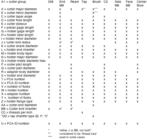
END MILL VISUAL AID PARAMETER REQUIREMENTS